In
this "how to" chapter, we deal with the mounting of the AN/AVS-9 bracket to the
helmet and replacing the Catseye mount. Second part deals with the mounting of the bracket
to the HGU-55/P. Before giving the technical information on how to replace the night
vision equipment, a little rundown of sets that has been in use:
AN/AVS-6 - Aviator’s Night Vision Imaging System (ANVIS) is the USN/USMC
rotary-wing aircraft NVG. There are currently over 3700 ANVIS NVG’s in service, with
an inventory objective of 4725. The Army and Air Force also use ANVIS. The AN/AVS-6 is a
lightweight, self-contained, helmet-mounted, direct-view binocular image intensification
device. ANVIS is powered by 2 AA alkaline batteries. It is a passive detection device
designed for use with military helicopters and KC-130 aircraft as a pilot aid during night
time, low-level terrain flight.
Used on H-53, H-1, H-46, H-3, H-60, KC-130 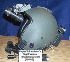
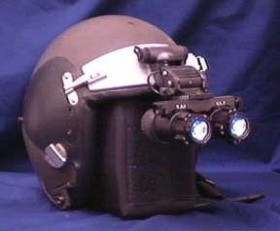
MXU-810/U - “Catseye” was
one of two NVG’s used in USN/USMC tactical (fixed-wing) aircraft. Catseye is
phased-out and replaced by AN/AVS-9. All Catseye NVG’s will be out of service by
2000. The MXU-810/U “Catseye” Night Vision Goggle Sensor (NVGS) was a
projected-image, helmet-mounted binocular image intensification device. Catseye utilised
an optical combined eyepiece to present the intensified image to the user. Catseye was
powered by one 1/2 AA lithium battery. It was a passive detection device designed for use
with military fixed-wing aircraft as a pilot aid during night time operations.
Was used on F/A-18, F-14, AV-8B.
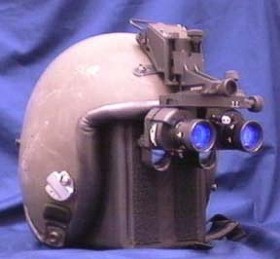
AN/AVS-9 - AN/AVS-9 is the new
USN/USMC tactical (fixed-wing) aircraft NVG. These goggles are currently being delivered,
with over 600 fielded to date and an inventory objective of 1450. AN/AVS-9 is also used by
the U.S. Air Force. The AN/AVS-9 is a lightweight, self-contained, helmet-mounted,
direct-view binocular image intensification device. AN/AVS-9 is powered by one 1/2 AA
lithium battery. It is a passive detection device designed for use with military
fixed-wing aircraft as a pilot aid during night time operations. Used on F-18C/D/E/F,
F-14A/B/D, AV-8B, F-18A/B (Pre-Lot 12 w/NVG Kits).
PART 1
SUBJECT: AN/AVS-9 (V), DETACHABLE HELMET MOUNTING PLATE ASSEMBLY INSTALLATION ON THE
HGU-66/P, HGU-68(V)/P AND THE HGU-85(V)/P HELMETS. (WUC 96C1P00)
PURPOSE OF DIRECTIVE:
The purpose of this directive is to provide P/N 264317-3,
AN/AVS-9(V) Detachable Helmet Mounting Plate Assembly installation instructions. This
change will provide aircrew members a means of attaching the AN/AVS-9(V) Night Vision
Goggle (NVG) to their protective helmet. Use of this NVG will provide a significantly
improved Field of View (FOV), thus enhancing overall aircrew night mission performance.
This technical directive was proposed in reference (a), approved by reference (b) and
authorized by reference (c).
APPLICATION:
1. BASIC EQUIPMENT:
a. The following equipment shall be modified by service activities:
Helmet Assembly, Medium HGU-66/P 97247 (NOTE 1) (NOTE 1) 750*
Helmet Assembly, Large HGU-66/P 97247
Helmet Assembly, Extra Lg HGU-66/P 97247
Helmet Assembly, Medium HGU-68(V)/P 97247 89D7981-1 01-393-1174 6000*
Helmet Assembly, Large HGU-68(V)/P 97247 89D7981-2 01-393-1182
Helmet Assembly, Extra Lg HGU-68(V)/P 97247 89D7981-3 01-393-1184
Helmet Assembly, Medium HGU-85(V)/P 97247 89D7981-7 (NOTE 2) 2500*
Helmet Assembly, Large HGU-85(V)/P 97247 89D7981-8
Helmet Assembly, Extra Lg HGU-85(V)/P 97247 89D7981-9
*Total quantity in use of each type helmet.
NOTES:
1. HGU-66/P Helmets one time procurement so no Part Number or NIIN assigned.
2. HGU-85(V)/P Helmets one time procurement so no NIIN assigned.
SUPPLY DATA:
1. REQUIREMENTS FOR BASIC EQUIPMENT:
a. Government Furnished Material (GFM):
1 264317-3 Helmet Mounting Plate Assy (extended travel)
1 265030-3 Bracket Kit, Helmet
b. Other Material Required:
1 GGG-K-275 Hex Key Set 00-439-8988 (2) $ 3.40
A/R Tape, Masking 00-283-0612 (2) N/A 1 inch wide
A/R Tape, Pressure 00-074-5124 (2) * N/A Sensitive, 1-inch wide
A/R MIL-A-46106 RTV 102/732 00-877-9872 (2) N/A Adhesive
1 89D7697-1 Lightweight 01-319-8962 (2) $49.76 Visor, Clear (for night) (NOTE 1)
(MBU-23/24/P trim)
1 89D7697-2 Lightweight 01-319-8961 (2) $48.57 Visor, Neutral (for day) (NOTE
1)(MBU-23/24/P trim)
*Tape required for step visor.
NOTE
One visor is required when using the MBU-23/24/P Oxygen Mask for only the HGU-68/P or
HGU-85/P Helmets.
c. Parts/Material Removed and Disposition:
1 88B7586-2 EEU7/P Helmet 8475-01-360-7285 (A) visor assembly
1 00-067-01 Helmet Plate 5340-99-780-0911 (A) assembly
DETAILED INSTRUCTIONS:
1. Basic Equipment:
NOTE
The Bracket Kit P/N 265030-3 contains required hardware to attach the P/N 264317-3 helmet
mounting plate to the selected helmet; four #6-32 hex head screws, four lock washers, left
hand- mounting bracket (thick concave bracket), right hand-mounting bracket (thin concave
bracket) and two interior backing plates. Ensure aircrew member has a properly fit helmet
assembly prior to incorporation of this directive.
a. Place all removed
components in a VIDS/MAF bag marked with the aircrew-members identification number. Set
aside and retain for future reconfiguration, as necessary.
NOTE (new note)
Prior to removal of the MXU-810/U Helmet Plate, outline the position of the Helmet Plate
on the helmet shell exterior surface to facilitate reconfiguration.
b. For HGU-66/P and HGU-85(V)/P helmets: Unsnap and remove visor; set aside clear of work
area for reinstallation. Detach existing MXU-810/U Night Vision Goggle helmet plate by
removing the three screws and flat washers along with fabric cover from the underlying
T-nuts. Proceed to step e.
c. For HGU-68(V)/P: Lower
visor to expose the visor locking guide-locking plate. Lift locking plate tab and slide to
open position to expose rounded hole in locking guide slot. Raise visor to full up
position placing visor lock knob in the rounded hole of locking guide slot. Rotate visor
lock knob 1/4 turn clockwise to disengage locking key from visor locking guide slot and
remove lock knob. Remove visor by sliding aft until clear of tracks.
d. Detach visor-locking guide by removing six attaching screws. Detach left and right
visor tracks and all external components by removing six attaching screws.
e. Detach ear cup assemblies from pile fastener tape on helmet shell interior and position
clear of work area.
f. Remove the screws and flat washers from the underlying lock washer and flanged nut
securing the chin/nape strap to the rear of the helmet, reassemble removed components on
grommeted ends of chin/nape strap to prevent twisting or position shift during
maintenance.
g. For HGU-66/P helmets: Position helmet inverted on workbench with the helmet brow
closest to technician. Grasp two fabric liner release loops on rear half of custom fit
liner, apply inward and upward pressure on loops, maintain pressure and move liner up and
out of rear of helmet shell. Slide front half of custom liner toward rear of helmet shell
and remove, set both halves aside for reinstallation. Proceed to step j.
CAUTION
The energy absorbing liner is easily damaged, use extreme care during removal and handling
procedures.
NOTE
Prior to removal of the energy absorbing liner, mark the centerline of the liner and the
helmet shell edge roll at the brow and nape to ensure correct re-positioning of the liner
during replacement.
h. For HGU-68(V)/P, HGU-85(V)/P helmets: Position helmet inverted on workbench with brow
of helmet closest to technician. Insert a thin flexible metal spatula (a 12-inch x 1-inch
metal ruler may be used) between inner surface of helmet shell and energy absorbing liner
at the center rear of the helmet, apply inward and upward pressure on liner, until there
is enough clearance to grasp energy absorbing liner with free hand.
NOTE
Rotate liner approximately 90 degrees left or right to clear ear cup cavity edge roll and
permit complete withdrawal from helmet shell
i. Maintain inward and upward pressure on liner and continue to move it up and out of
helmet shell.
j. For HGU-66/P and HGU-85(V)/P helmets: Invert helmet and place 1 inch x 1 inch squares
of pressure sensitive tape on the three t-nuts and underlying lock washers securing the
MXU-810/U helmet plate on the helmet shell interior surface. place helmet upright on work
bench with front of helmet closest to technician. detach MXU-810/u helmet plate from
helmet shell exterior by removing the three screws and flat washers along with fabric
cover from the underlying lock washers and t-nuts.
k. HGU-66/P, HGU-68(V)/P, HGU-85(V)/P: Place helmet upright on workbench with the front of
helmet closest to technician. Adjust helmet-mounting plate left hand-latching screw
counterclockwise until lower end of screw is flush with the inner end of the integral
threaded cylindrical nut, with the locking nut loosened. Position helmet-mounting plate
across brow of helmet, with helmet plate lower edge extension resting level across the
upper edge of helmet shell brow edge roll. Align mounting plate centering arrow with
center of upper MXU-810/U helmet plate-attaching slot. (1) Visually verify alignment of
helmet mounting plate-centering arrow with upper attaching slot and that the lower edge
extension is resting on the upper edge of the helmet shell edge roll. Hold mounting plate
firmly in place on helmet brow and tape in place with masking tape applied
to the mounting plate and helmet shell on the left and right side of the goggle mount. (2)
Position helmet with left hand side to technician. Lift “over center” latch and
insert head of latching screw into the center cut-out of the left hand mounting bracket
(thick concave bracket), close “over center” latch, ensuring head of latching
screw remains centered in left-hand bracket
cut-out.
(3) Position concave surface of left mounting bracket flush with surface of helmet shell,
with head of latching screw centered in cut-out, inner edge of mounting bracket parallel
to the left edge of the helmet mounting plate. Holding bracket in place, outline mounting
bracket position on exterior helmet shell surface, place a mark at the center of the upper
and lower slots to
indicate location of drilling points for attaching screws.
NOTE
The right hand mounting bracket features two latching notches, one deep notch and one
shallow notch, with four attaching screw slots. These features are incorporated to permit
minor adjustments to the helmet mounting plate assembly’s position on the helmet
shell exterior surface to individualize goggle placement to optimize eye relief and
interpupillary distance adjustments for the aircrew member.
(4) Position right hand side of helmet toward technician. Position right hand mounting
bracket with shallow latching notch down and away from front center of helmet under
latching hook, engage right hand helmet mounting plate-latching hook into bracket
notch.
(5) With firm downward pressure on hook, position concave surface right hand mounting
bracket flush with exterior surface of helmet shell. With shallow locking notch down and
away from center of helmet and inner edge of mounting bracket parallel with right edge of
helmet mounting plate, hold bracket in place and outline bracket position on exterior
helmet surface, place a mark at the center of the upper and lower attaching slots, closest
to the shallow locking notch, to indicate location of drilling points for attaching
screws.
(6) Remove masking tape from helmet shell and mounting plate, set mounting plate aside
clear of work area.
l. At each of the two marked locations on each side of the helmet, using a No. 33 (.113)
drill bit, drill a small pilot hole. Using a No. 16 drill bit, enlarge each pilot hole to
finished .177 dimension.
NOTE
Apply a small amount of RTV to the first few threads of attaching screws of the left hand
mounting bracket prior to installation. Application of RTV to the right hand mounting
bracket-attaching screws will be accomplished after final goggle fit and alignment checks.
m. Position backing plate, with flat surface of backing plate toward interior surface of
left hand side of helmet align built in nuts with two drilled left-hand bracket holes. On
the left side exterior, position left hand bracket, with center cutout toward top of the
helmet, over drilled holes. Secure in place using a 5/64 inch hex head key and two screws
and lock washers. Repeat procedure for installation on right hand bracket, ensuring the
center notch is down and away from top of helmet.
n. Engage the right hand latching hook into the notch of the right hand mounting bracket,
fit the left hand-latching screw into the center cut-out of the left hand mounting bracket
and close the “over center” latch. If helmet mounting plate assembly is loose,
adjust left hand latching screw to provide the desired tension, ensuring the helmet
mounting plate assembly is centered on helmet, when the over center latch is closed. Once
desired is achieved, tighten lock nut to maintain proper position of latching screw.
o. For HGU-66/P helmet: Invert helmet on work bench with brow positioned closest to
technician. From rear of helmet, ensuring liner half remains centered within the helmet
shell interior, insert front half of custom fit liner firmly against helmet shell brow
edge roll. Insert back half of custom fit liner, with fabric release loops positioned to
the right and left side, ensuring the liner half remains centered within the helmet shell
interior, into rear of helmet and push into place. Using screws, flat washers , locking
washers and flanged nuts, install grometted ends of chin/nape strap to rear attaching
points on helmet shell. Attach ear cups to pile fastener fabric on interior of helmet
shell ear cup cavity.
p. For HGU-68(V)/P, HGU-85(V)/P helmets: Reinstall internal components in accordance with
paragraph 13A-75, steps 2 a. through step 6.
NOTE
During the aircrew member goggle fit process, if difficulty is experienced in obtaining
proper eye relief or interpupillary distance using installed goggle adjustments, minor
adjustments to the position of the helmet mounting plate assembly may be accomplished by
means of attaching slot selection. To adjust position of helmet mounting plate assembly
slightly
to the right (as worn), place screws in the inboard attaching slots. To adjust position of
helmet mounting plate assembly slightly to the left (as worn), install the mounting
bracket with the deep notch down and away from the center of the helmet, using the
attaching slots closest to the deep notch.
PART 2
HGU-55/P HELMET MODIFICATION KIT INSTALLATION (NSN 5340-01-442-6411)
INTRODUCTION
This document provides instructions on how to install and adjust the left and right
mounting brackets on the HGU-55/P Helmet. This installation procedure is advisory for
user/installer's convenience.
NOTE
In case of conflict, USAF T.O. 14P3-4-151 takes precedence over this document.
1. Remove the TPL Cover Assembly.
2. Remove the energy absorbing liner.
3. Locate the holes underneath the leather on the left side of the helmet. With your
fingers press on the leather and find hole 1 which is the closest hole to the inside
corner of the helmet (see figure 1). On some helmets this hole may be just at the border
of the edge roll.
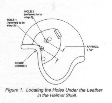
4. Using a spring loaded
punch, punch a hole in the leather that covers the hole found in step 3. Using a 3/16
(.1875) bit, drill out the hole.
5. Locate hole 2 with your fingers by moving them along the helmet approximately 1 3/8
inches to the upper right of hole 1 (see figure 1).
NOTE
On some helmets, the second hole is more than 1 3/8 inches from the first hole. If this is
found to be the case. The second mounting hole must be drilled in the helmet as explained
in the following steps.
6. Place the left side mounting bracket (264345) on the helmet with the concave side
against the helmet and the notched side towards the front of the helmet.
7. Align the mounting bracket screw hole with the hole drilled in step 4. Position the
bracket along a line from the first hole, to the second hole (see figure 2). Using a
spring loaded punch mark the position for the second hole.
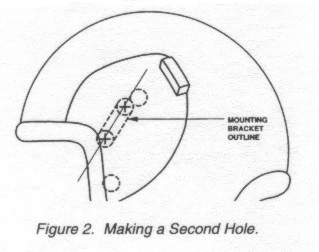
8. If necessary, use a 3/16
(.1875) inch bit and either drill out the existing hole or drill the required new hole.
9. Repeat steps 3 through 8 for the right side of the helmet using the left mounting
bracket as an aid.
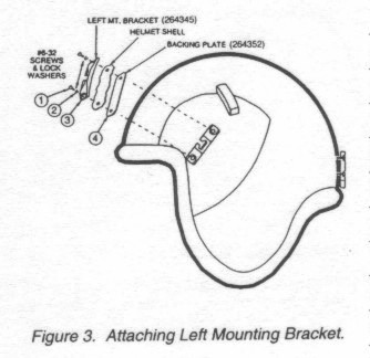
10. Position the left side mounting bracket (264345) on the outside of the helmet, concave
side against the helmet and the open end of the notch toward the helmet center line (see
figure 3) and one of the backing plates (264352) on the inside of the helmet. Secure them
in place using two screws and two lock washers. Do not tighten at this time.
NOTE
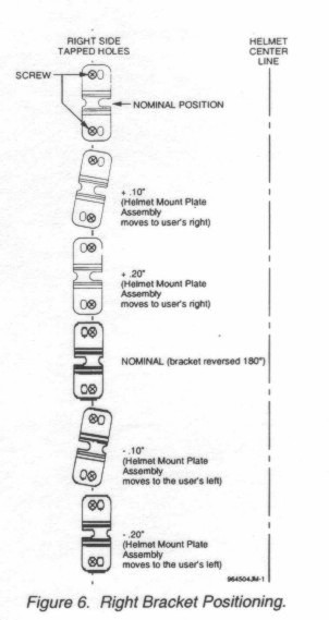
The right mounting bracket has adjustment capabilities that will be explained in step 16.
The right mounting bracket can de secured, but not tightened (at this time), in either of
the two nominal positions illustrated in figure 6.
11. Repeat step 10 for the right mounting bracket (see figure 4).
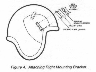
12. Position each bracket such
that the holes in the brackets are approximately centred under the screw. Using a 5/64
inch Allan wrench, tighten the four screws.
13. Locate the centre line of the helmet. Mark a position approximately 2 to 2 1/2 inches
up along the centre line from the border of the edge roll.
CAUTION
The helmet mount plate assembly may be damaged if the following adjustment procedure is
not used.
14. Lift the handle of the left side catch assembly so that the handle is in the position
shown in figure 5.
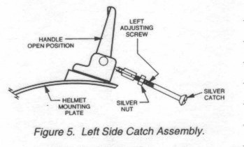
15. On the left side catch
assembly (figure 5); loosen the silver nut on the adjusting screw to allow the adjusting
screw to move.
16. Engage the helmet mount plate assembly right side hook to the right mounting bracket
and place the helmet mount plate assembly on the helmet ensuring the moulded arrow on the
helmet mount plate assembly is aligned with the helmet centre line.
NOTE
The right mounting bracket is designed to allow the helmet mount plate assembly to be
moved ±0.20 inches laterally across the helmet. This is to accommodate variations in
helmets as well as users hose facial features require the helmet mount plate assembly to
be offset from the centre line of the helmet. Figure 6 illustrates the different positions
of the bracket and mounting screws necessary to achieve the lateral adjustment of the
helmet mount assembly.
17. Position the helmet mount
plate assembly's silver catch into the left mounting bracket. Close the catch assembly
noting that excessive pressure should not be required. The adjusting screw may require
adjustment in order to achieve a firm but not excessively firm closing pressure. Once
adjusted, tighten the silver nut so that the left adjusting screw will not move.
18. Replace the energy absorbing liner.
19. Replace the TPL Cover Assembly. |